.png)




Author | SHENGWO Industry Insights Team
Updated | September 2026
Contents
Sheet metal design tolerances have a direct impact on manufacturing cost, assembly performance, product quality, and production consistency.
For engineers and product designers, setting tolerances too tightly may significantly increase fabrication costs. On the other hand, tolerances that are too loose—or missing entirely—can lead to assembly problems, misaligned holes, dimensional variation, and inconsistent product performance.
This is particularly important for custom sheet metal fabrication, where laser cutting, punching, bending, welding, and finishing processes each have different levels of dimensional capability.
So, how should engineers define sheet metal tolerances correctly?
Before releasing a drawing for production, it is useful to review four key areas:
Let’s look at each point in detail.
One of the most common problems in sheet metal manufacturing is unclear or unnecessarily tight tolerance requirements.
For example, if a drawing applies extremely tight tolerances to almost every dimension, the manufacturer may need additional machining, special tooling, extra inspection, or slower production processes.
This can increase manufacturing costs without necessarily improving the final product.
At the same time, the opposite problem can occur. If important functional dimensions do not have appropriate tolerances, the finished parts may not assemble correctly.
Not every dimension on a sheet metal drawing needs the same tolerance.
For example, a cosmetic outer dimension that does not affect assembly may not require the same tolerance as:
A practical drawing should distinguish between critical functional dimensions and general dimensions.
When individual dimensions do not have specific tolerances, the drawing should clearly define a general tolerance standard.
Depending on the applicable design and manufacturing standard, a drawing may reference a general tolerance specification such as ISO 2768 or another applicable standard.
The important point is not simply to add a tolerance standard to the drawing. The selected tolerance should also match the actual manufacturing process and product requirements.
Tolerance accumulation becomes particularly important when multiple holes or features are positioned over a relatively long distance.
For example, if a sheet metal panel contains a long row of mounting holes, small positional variations can accumulate along the length of the part.
A design that looks correct in CAD may therefore create assembly difficulties when several components must be aligned.
This is why tolerance analysis should be considered during the design stage rather than after production begins.
The goal of sheet metal tolerancing is not to make every dimension as precise as possible. It is to achieve the required product function at a reasonable manufacturing cost.
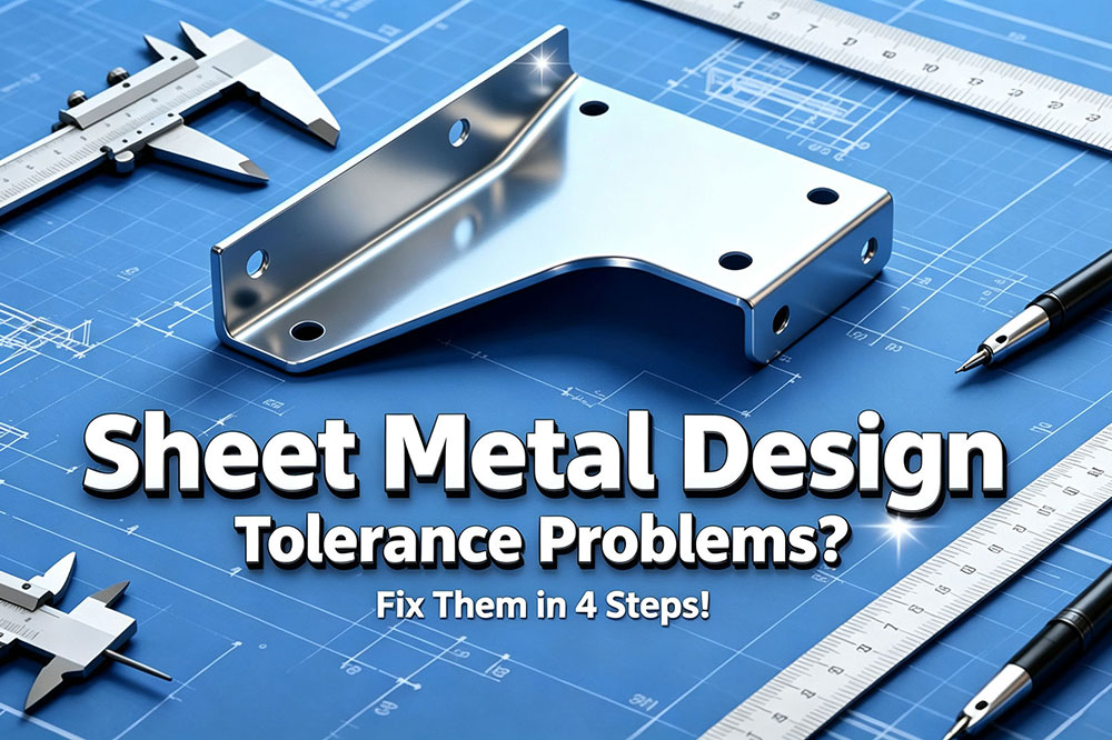
Bending is fundamentally different from CNC machining.
A CNC machining process can remove material with highly controlled tool movement, while sheet metal bending involves material deformation. Factors such as material thickness, material properties, bend radius, tooling, springback, machine capability, and bending sequence can all affect the final dimensions.
Therefore, applying machining-level tolerances to every sheet metal bend may be unrealistic and unnecessarily expensive.
As a general reference, sheet metal bending dimensions may commonly fall within approximately ±0.2 mm to ±0.5 mm, depending on the material, thickness, geometry, machine, tooling, and specific production conditions.
These figures should not be treated as universal specifications.
Actual bending accuracy depends on:
For high-volume production, the supplier should evaluate the actual component geometry before confirming achievable tolerances.
If a bent flange must mate with another component, the design should consider how much dimensional variation the assembly can tolerate.
In some applications, designers can introduce features that absorb small manufacturing variations.
For example:
These design features can make the final assembly more tolerant of normal manufacturing variation.
Instead of requiring extremely tight bending tolerances, it is often more practical to design an assembly that can accommodate controlled dimensional variation.
After bending, sheet metal tends to partially return toward its original shape. This phenomenon is known as springback.
The amount of springback can vary depending on:
Professional sheet metal manufacturers compensate for springback through process settings and tooling adjustments.
However, designers should still understand that bending is a forming process rather than a machining process.
Understanding actual bending capability is the foundation for setting practical sheet metal tolerances.
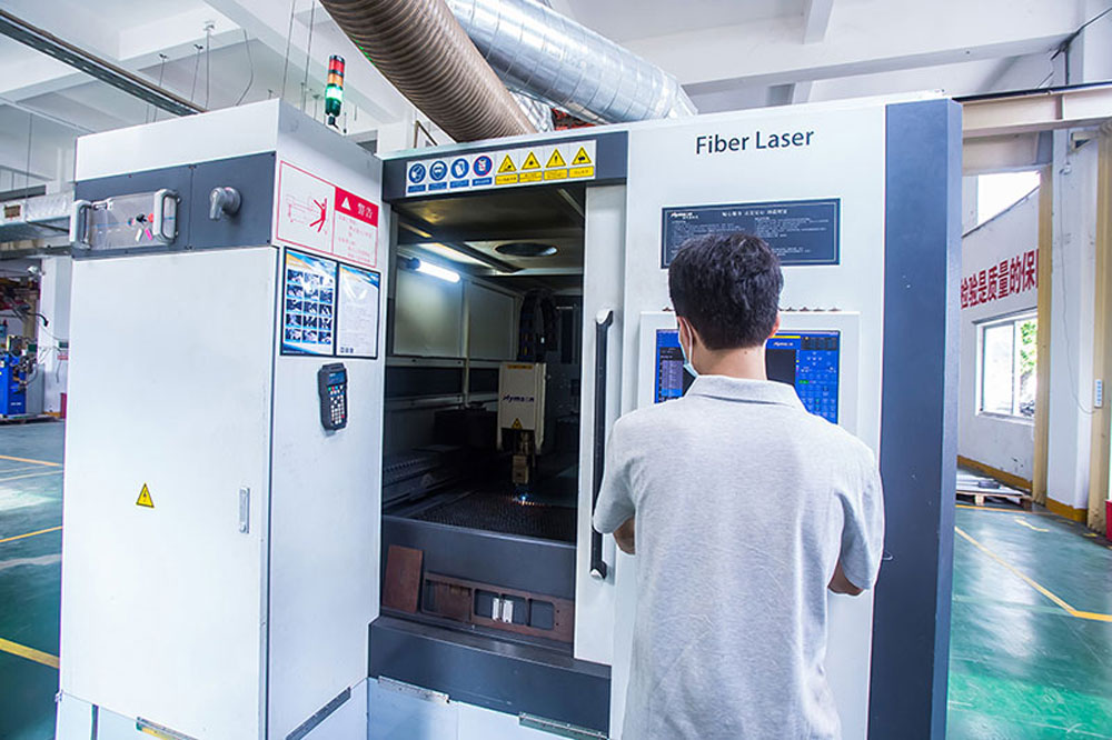
Hole positioning is one of the most important areas to consider when designing sheet metal parts for assembly.
A common design problem occurs when two components each contain a long row of corresponding mounting holes.
On a CAD drawing, every hole may appear perfectly aligned.
In real production, however, every cutting, punching, bending, and positioning operation has some degree of variation.
When multiple dimensions are chained together, these small variations can accumulate.
Imagine two long sheet metal panels that need to be assembled together.
If both panels have ten matching holes and every hole must align precisely, even a small dimensional difference along the length can make the final holes increasingly difficult to align.
This is a classic tolerance accumulation problem.
Instead of simply tightening every hole-position tolerance, engineers should consider whether the assembly itself can be designed to absorb positional variation.
One practical approach is to use a round hole as a primary locating feature.
The round hole establishes the reference position of the component.
A second hole or series of holes can then use a different geometry to accommodate dimensional variation.
Slot holes, also called elongated or slotted holes, are widely used in sheet metal design when some positional adjustment is required.
For example:
This approach can make assembly easier without requiring extremely tight tolerances throughout the entire part.
In some applications, floating nuts or other compliant fastening solutions can provide additional positional flexibility.
These solutions are especially useful when:
The key principle is simple:
Do not solve every assembly problem by tightening manufacturing tolerances. Sometimes the better solution is to improve the design.
Welding introduces another important consideration for sheet metal design.
Compared with laser cutting or CNC machining, welding can introduce additional dimensional variation because localized heat causes thermal expansion and contraction.
As a result, welded assemblies should generally not be treated like precision-machined components.
During welding, heat is concentrated around the weld area.
As the material heats and subsequently cools, it can deform or move slightly.
The amount of deformation depends on factors such as:
For large welded structures, these effects can become more significant.
A common design mistake is specifying extremely tight overall dimensions, hole spacing, or flatness requirements for a welded assembly without considering the welding process.
If a welded structure requires a critical dimension to be extremely accurate, the manufacturer may need additional processes to achieve the final requirement.
This can include:
For welded structures requiring high-precision interfaces, designers can consider leaving appropriate machining allowance on critical areas.
The general manufacturing sequence may be:
Cutting → Forming → Welding → Stress/Distortion Control → CNC Machining → Final Inspection
This allows welding to create the structural assembly while CNC machining establishes the final critical dimensions.
For example, if a welded frame needs a precision mounting surface, it may be more practical to machine that surface after welding instead of requiring the welding process itself to achieve machining-level flatness.
This approach can provide better control over critical dimensions while keeping the overall manufacturing process realistic.
One of the most important principles in sheet metal design is that tolerance requirements should be based on actual manufacturing capabilities.
Different processes naturally have different levels of precision.
| Manufacturing Process | Typical Application |
|---|---|
| Laser cutting | Profiles, holes, contours and flat sheet features |
| Punching | Repetitive holes and sheet metal features |
| Sheet metal bending | Flanges, angles and formed components |
| Welding | Structural assemblies and fabricated frames |
| CNC machining | High-precision interfaces and critical dimensions |
| Grinding | Fine surface and dimensional requirements |
This means a single component may require different tolerance strategies for different features.
For example, a fabricated enclosure may use laser cutting for the flat panels, bending for the flanges, welding for brackets, and CNC machining for a critical mounting surface.
Trying to achieve the same tolerance level across all processes may unnecessarily increase cost.
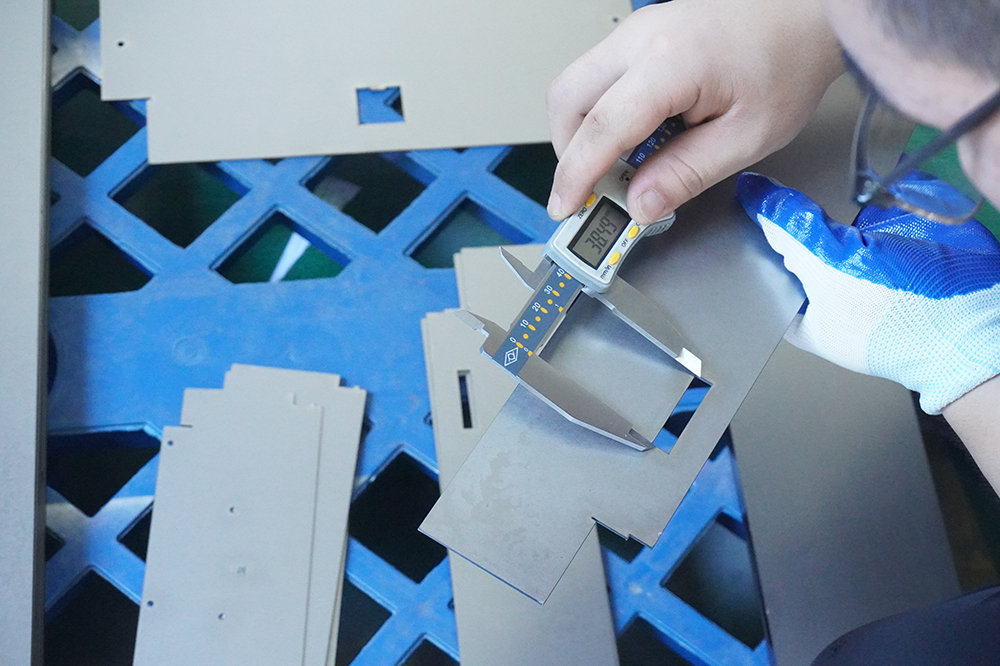
Good tolerance design should begin before production.
When preparing a drawing for a custom sheet metal fabrication project, engineers should consider the following:
Clearly identify dimensions that directly affect:
These dimensions deserve more attention than non-functional dimensions.
Tighter tolerances generally require greater process control and may increase inspection and manufacturing costs.
Only specify tight tolerances where they are functionally necessary.
The manufacturing process can affect dimensional accuracy.
For example:
Laser Cutting → Bending → Welding → Machining
will produce different dimensional results from a process that uses machining before welding.
Use practical features such as:
These can reduce the need for unnecessarily tight manufacturing tolerances.
If a component requires unusually tight tolerances, it is better to discuss the requirement with the manufacturer during the design stage.
An experienced supplier can determine whether the requirement can be achieved through:
Early communication can prevent expensive redesigns after production begins.
SHENGWO MACHINERY provides custom sheet metal fabrication, CNC machining, HVAC dampers, custom supermarket shelving, electrical panels and metal components for global OEM and industrial customers.
Our manufacturing capabilities include:
For custom projects, customers can provide drawings, 3D CAD files, material requirements, surface treatment specifications, tolerances, quantities, and assembly requirements.
Our engineering team can review the drawings before production and evaluate important manufacturing considerations such as:
For components that combine sheet metal fabrication and CNC machining, we can also evaluate which features should be produced through fabrication and which critical features may require secondary machining.
This process helps align the engineering design with actual manufacturing capabilities.

Q1:What are typical sheet metal tolerances?
There is no single tolerance that applies to all sheet metal components. Actual achievable tolerances depend on the manufacturing process, material, thickness, geometry, equipment, tooling, and inspection method.
For sheet metal bending, a general reference range may be around ±0.2 mm to ±0.5 mm, but specific projects should be evaluated based on their actual geometry and requirements.
Q2:Should all sheet metal dimensions have tight tolerances?
No. Tight tolerances should generally be reserved for functional or critical dimensions. Applying unnecessarily tight tolerances to every dimension can increase manufacturing cost without providing additional functional value.
Q3:How can tolerance accumulation be reduced in sheet metal assemblies?
Designers can use appropriate datum structures, round locating holes, slot holes, floating fasteners, and adjustable mounting features. These methods allow the assembly to absorb controlled dimensional variation.
Q4:Can welded sheet metal parts achieve high precision?
Welded assemblies can achieve controlled dimensional accuracy, but welding introduces thermal deformation. When higher precision is required, critical surfaces or holes may be machined after welding.
Q5:What information should be included on a sheet metal drawing?
A good drawing should clearly specify material, thickness, dimensions, general tolerances, critical tolerances, bend requirements, hole specifications, surface treatment, welding requirements, and other functional requirements.
Good sheet metal tolerance design is not about making every dimension as precise as possible.
It is about finding the right balance between function, assembly requirements, manufacturing capability, quality, and cost.
Before sending a sheet metal drawing to production, check these four areas:
When designers understand the capabilities and limitations of laser cutting, bending, welding, and CNC machining, they can create parts that are easier to manufacture, easier to assemble, and more cost-effective to produce.
Have a custom sheet metal project?
Send your drawings or 3D CAD files to SHENGWO MACHINERY for engineering review and quotation.
From precision sheet metal fabrication and CNC machining to welding, surface treatment, and assembly, we support OEM customers from drawing review to finished components.
SHENGWO MACHINERY — From your drawings to reliable manufactured parts.
No. 8803 Zhuhai Road, LianWan Industry Park, Jinwan District, 519090 Zhuhai, Guangdong, China